


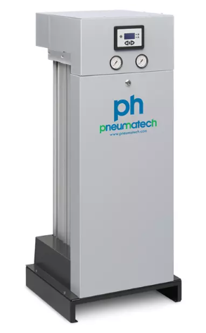
Pneumatech PH 55-550 S
PDP Options and Manifold System
PH 55–550 S adsorption dryers are available in two PDP variants: –20 °C/–4 °F and –40 °C/–40 °F.
The unique manifold system (patent pending) includes pilot air-operated 3/2-way valves that switch quickly and reliably.
Durable Design and Desiccant Configuration
The desiccant is spring-loaded and housed in a robust aluminium profile vessel that withstands up to 14 barg/203 psig pressure (fatigue load). Each dryer comes standard with pre- and after-filters.
Efficient Operation and Smart System Monitoring
Operating costs are always optimised thanks to standard compressor synchronisation, purge nozzle optimisation, and optional PDP control. The full machine status can be monitored via the controller display and pressure gauges. The controller indicates whether the power is connected, towers are pressurised, valves operate correctly, or preventive maintenance is needed. If optional PDP control is connected, the PDP value can be shown on the display. Alarms and warnings can also be transmitted remotely using volt-free contacts.
Why choose the PH 55–550 S series?
-
Advanced energy management for lowest operating costs
-
High reliability and low maintenance thanks to unique valve design
-
High-quality desiccant ensures stable pressure dew point (PDP)
-
Advanced controller for continuous machine status monitoring
-
Spring-loaded desiccant reduces risk of crushing
-
Counterflow regeneration for maximum energy efficiency
-
Designed for easy transport and installation
-
Desiccant bags allow easy top-loading maintenance
PH 55 S to PH 550 S technical specifications (standard version, PDP –40 ˚C)
Fill in the contact form here or feel free to give us a call!